
Tru Blu installation & ownership guide
Positioning the pool
Set the shell on its prepared base with the fittings facing the planned service routes.
Use this guide with the installation detail and equipment manuals supplied with your pool. Your site approval sets the required inspections.
Before moving
- Check the foundation is ready, level and clean. Compare the final position with the approval plan.
- Identify the intended skimmer, return and lighting orientation before placement so pipes and cables follow the planned route.
During placement
- Use the supplied handling method and a competent handling provider. Keep the shell coating protected from slings, edges and building debris.
- Lower onto the bearing surface evenly. Do not drag the shell across gravel or lever it from fittings.
After placement
- Check full contact with the base and level across the shell. Resolve any rocking, void or uneven support before water is added.
- Keep deck posts and surrounding soil from pressing against the shell. Preserve access to the skimmer and all service connections.
Before connections
- Photograph the base and shell position for your records.
- Confirm safe access, barrier arrangements and equipment routes before fixing pipework or filling.
Illustrated installation manual
Work through the drawings and job checks below, or download the same sequence as a PDF. Open a drawing to zoom into its labels.
01Your installation sequence
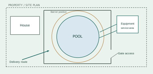
- Choose the pool position, fittings orientation and equipment location together. Draw the barrier and gate on the same plan.
- Arrange the approval pathway and inspection schedule. Eligible NSW projects may use a CDC through a registered independent certifier or council; we can advise upon purchase.
- Locate buried services and overhead hazards. Keep excavation and delivery routes clear of them.
- Prepare the foundation and drainage; place the shell; connect equipment; arrange licensed electrical work; complete barriers and commissioning.
Site diagram is a planning aid. It does not establish setbacks or barrier dimensions.
02Mark the footprint
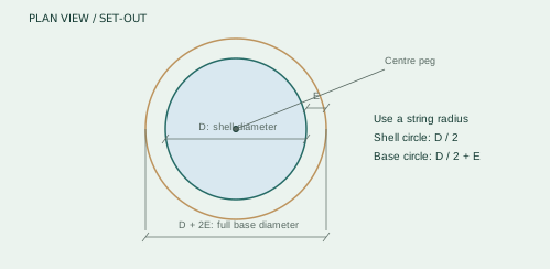
- Set a centre peg and mark the shell circle using a radius of D / 2. Check the chosen diameter against your order.
- Mark a second circle for the full supporting foundation: outside diameter D + 2E. E is the edge extension in the foundation detail for this installation.
- Set finished base height with a laser and reference peg that will remain visible during excavation and compaction.
- Mark the fittings side before placement so the pipe routes are short, accessible and clear of the barrier.
| Pool | D | Radius | Foundation diameter |
|---|---|---|---|
| Compact | 2,200 mm | 1,100 mm | 2,200 + 2E mm |
| Classic | 2,800 mm | 1,400 mm | 2,800 + 2E mm |
| Family | 3,400 mm | 1,700 mm | 3,400 + 2E mm |
D is the ordered shell diameter. E and base depth T are construction dimensions from the foundation detail.
03Construct a compacted granular base
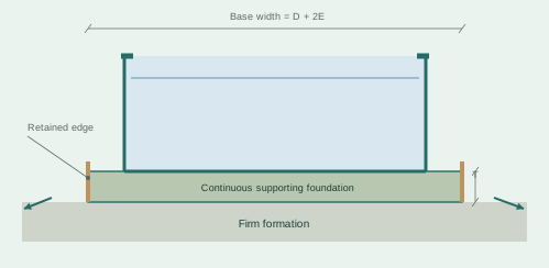
- Strip grass, roots, organic topsoil and soft pockets. Establish firm formation across the whole marked footprint.
- Place the specified granular material in manageable layers. Moisture-condition and compact each layer with suitable equipment; do not compact only the top of a loose heap.
- Trim the finished surface flat and level. Check several crossing directions with the laser or straightedge, including the perimeter.
- Retain the outside edge so rainfall and splash water cannot erode the base. Keep the retaining edge outside the shell bearing line.
- Remove sharp protrusions, debris and isolated high spots before placement. Photograph the finished base.
- Foundation material / depth T
- Edge extension E
- Finished base level
- Level check results / date
The prototype site drawing used a 100 mm compacted DGB20 road-base layer. That is a site example, not a universal slab or soil specification.
04Concrete, runoff & services
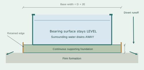
- Where the site detail specifies a reinforced slab, set its size, reinforcement, thickness, cover and curing sequence before the pour. Keep the bearing surface level.
- Slope surrounding ground and paths away from the level pool base. Divert downpipes and uphill runoff so they do not discharge beneath it.
- Locate the equipment on a stable, drained pad. Keep pump lids, filter cartridges, UV lamps, valves and electrical isolation accessible.
- Route trenches outside the supporting footprint unless the construction detail provides for them. Reinstate and compact disturbed ground.
- Drainage route / discharge point
- Equipment pad location
- Pipe route / trench record
A drainage slope belongs around the foundation, not across the pool bearing surface.
05Delivery, unloading & placement
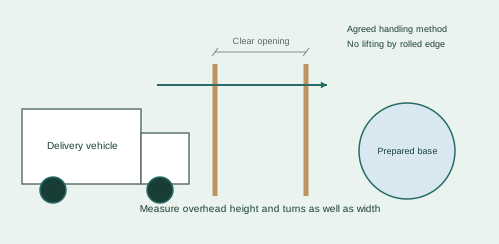
- Measure the narrowest gate, path, overhead opening and turning area. Send photographs and measurements when arranging freight.
- Agree the vehicle position, unloading responsibility and lifting method with the carrier before dispatch. Book lifting services separately where required.
- Inspect packaging and shell on arrival; record visible damage before accepting handover. Keep all handling equipment away from the rolled edge and fittings.
- Lift and place using the agreed handling method. Do not drag the shell over rough ground or use pipe fittings as handles.
- Orient the fittings, then check complete base contact and level. Correct the base while the shell is empty; do not pack isolated supports underneath.
- Narrowest access width / height
- Carrier / unloading method
- Placement level check
- Delivery condition / photographs
Shell weight and lifting attachment locations are delivery-specific. The rolled edge is not a lifting point.
Manufacturer instructions & references
Keep the instructions for your exact supplied model with this guide.
NSW pool approval pathways ↗Completion checklist
- Shell orientation correct
- Coating and fittings undamaged
- Base contact and level checked
- No external loading against shell
Help when you need it.
Installing the kit yourself or coordinating trades? Send your order number, photographs and the step you need help with.
contact@trublupools.com.au ↗