
Tru Blu installation & ownership guide
Plumbing connections
Connect the supplied circulation equipment with supported pressure pipework and accessible isolation points.
Use this guide with the installation detail and equipment manuals supplied with your pool. Your site approval sets the required inspections.
- 1Pool outlets
- 2Pump
- 3Filter
- 4UV chamber
- 5Pool returns
Use your supplied connection drawing for pipe sizes, valves and any heating circuit. This sequence is an overview, not a fitting-position template.
1. Identify the circuit
- Use the connection drawing supplied with your order to identify suction from the pool, pump inlet, pump discharge, filter, UV unit and return to the pool.
- The flow illustration is a circulation overview, not a drilling template. Keep the supplied suction outlets, covers and connection arrangement intact.
2. Dry-fit and support
- Measure the actual route and dry-fit the required pressure-rated pipe, elbows, unions and valves before making permanent joints.
- Use the pipe sizes and adapters shown in your supplied layout. Support long runs and changes of direction independently so the shell fittings do not carry pipe weight.
3. Make connections
- Prepare, join and cure solvent-welded PVC connections exactly as the pipe and adhesive suppliers instruct. Keep debris and excess adhesive out of equipment.
- Seat supplied union seals cleanly and tighten as the equipment manual specifies. Do not glue a service union shut or overtighten plastic threads.
4. Account for upgrades
- A heating upgrade needs its manufacturer connection layout, isolation/bypass arrangement and specified flow. Follow the layout supplied for your package.
- A cartridge filter does not backwash like a sand filter. Any overflow, pool draining or site drainage connection still needs a suitable lawful discharge route.
5. Commission
- Use the specified water-based commissioning method to check for leaks. Do not improvise compressed-air pressure testing of plastic pool equipment.
- Open the required circulation valves, prime the pump and check each connection during startup. Record leaks and rectify them before normal use.
Joint materials and service connections
- Separate solvent-welded PVC pressure-pipe joints from ABS shell fittings and O-ring barrel unions. Identify the material and supplied fitting model before choosing cement.
- Spa Electrics Pro-Suction instructions specify clear non-pressure Type-N cement at that fitting and advise against Type-P there. This does not change the cement required for ordinary PVC pressure-pipe joints.
- Davey CrystalClear barrel unions seal on clean, seated O-rings and are tightened by hand. Do not glue the union, add silicone to it or tape the O-ring sealing face.
Illustrated installation manual
Work through the drawings and job checks below, or download the same sequence as a PDF. Open a drawing to zoom into its labels.
01Read the circulation circuit
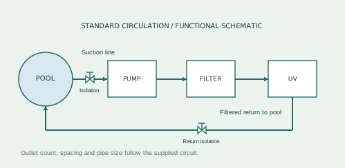
- Identify the supplied suction arrangement and return connection on the pool. Keep the whole engineered suction layout intact.
- Trace suction to the pump inlet; pump discharge to the filter inlet; filtered water through the UV return circuit and back to the pool.
- Mark flow arrows on the pipework and label accessible valves. The diagram shows function, not the drilling position or number of suction outlets.
- If heating is selected, use the heater branch shown on the next page and the installation drawing supplied with the kit.
No spa-jet circuit is included in the standard package. Do not add a pump or outlet branch without the corresponding system design.
02Heating branch & isolation
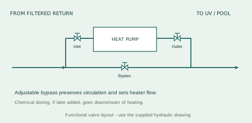
- Install the heat pump in the filtered return circuit with the specified adjustable bypass. Match the actual IN and OUT markings.
- Provide service isolation and unions where shown, with room to remove each unit without cutting surrounding pipework.
- Keep the UV upstream of any additional sanitising device. Any later chemical dosing belongs downstream of the heat pump.
- Leave the bypass controls accessible and label their commissioning setting. Isolating the heater must not accidentally stop all normal pool circulation.
This is a functional three-valve bypass illustration. A supplied three-way-valve layout may differ while serving the same purpose.
03Measure, cut & prepare each joint
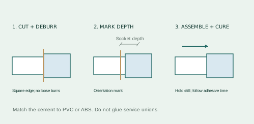
- Lay out equipment and dry-fit pipe lengths before gluing. Account for the socket insertion depth at both ends of each piece.
- Cut square, remove burrs inside and out, and clean mating surfaces. Mark the insertion depth and final orientation on the pipe.
- Check the adhesive for the materials being joined. Ordinary PVC pressure joints and ABS shell fittings must not be treated as interchangeable.
- Apply, assemble, hold and cure each solvent joint to the adhesive instructions. Keep the joint still while it sets; do not fill early.
For Spa Electrics Pro-Suction, the manufacturer specifies clear Type-N cement at the fitting and advises against Type-P. Use the correct pressure-pipe adhesive elsewhere.
04Support the pipes; preserve the seals
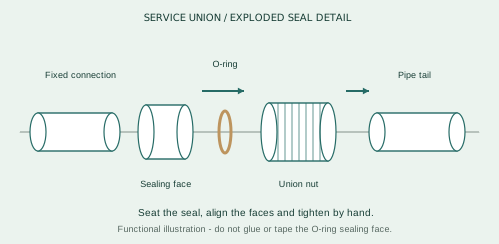
- Support pipe weight independently near equipment and changes of direction. A union or shell fitting should not be pulled sideways to make an awkward run fit.
- For Davey O-ring barrel unions, inspect the seal and groove, use compatible O-ring lubricant where instructed, align the mating faces and tighten by hand.
- Leave unions, isolation handles and drain points accessible. Mark buried routes and photograph them before covering.
- Check the pipe sizes against the circuit detail. Davey CrystalClear requires 50 mm pipe where piping length exceeds 15 m.
Do not put solvent cement, silicone or thread tape on an O-ring union sealing face.
05Wet-test and record the circuit
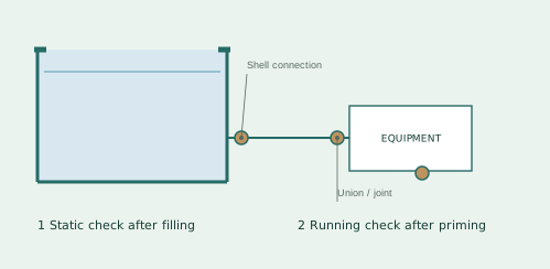
- Complete required inspections before pipework is covered. Allow every adhesive and sealant its specified cure time.
- Fill to the operating waterline, inspect the shell fittings under static water load, then prime and run the pump to inspect the moving-water circuit.
- Check suction for persistent air entry and returns for leaks. Inspect every union, fitting and supported joint with access unobstructed.
- Stop and isolate before correcting a leak. Depressurise filter equipment before opening it. Never use compressed air to test the filter.
- Suction / return pipe size
- Adhesive and cure completion
- Static leak check
- Running leak check
- As-built photographs / valve labels
Start equipment only with the correct water supply and valve positions.
Manufacturer instructions & references
Keep the instructions for your exact supplied model with this guide.
Spa Electrics fitting manuals ↗Davey equipment manuals ↗Completion checklist
- Suction and return lines correctly identified
- Pipework independently supported
- Service unions and isolation accessible
- Joints cured and seals seated
- Circuit leak checked
Help when you need it.
Installing the kit yourself or coordinating trades? Send your order number, photographs and the step you need help with.
contact@trublupools.com.au ↗