
Tru Blu installation & ownership guide
Heat pump installation
Prepare an outdoor position and install the optional Insnrg Hi35 to the supplied heating layout.
Use this guide with the installation detail and equipment manuals supplied with your pool. Your site approval sets the required inspections.
Position and airflow
- Use a stable outdoor base and keep the air intake and discharge clear to the distances in the exact supplied Hi manual.
- Allow access for service and condensate drainage. Avoid a confined enclosure or a position that recirculates cold exhaust air. Consider neighbour noise and local requirements.
Water connections
- Use the supplied heating circuit, pipe sizes and bypass/isolation arrangement. Match the unit’s required flow and protect it from debris.
- Support connections and check the circuit for leaks before operation. Keep the heat pump accessible for isolation and winter care.
Electrical and installer work
- Use a qualified installer and licensed electrical work as required by the manufacturer. The electrician must size the circuit from the unit rating and site conditions.
- Refrigeration work is for a licensed refrigeration mechanic; do not open the refrigerant circuit as a DIY task.
Commissioning
- Establish filtration flow before enabling heating. Verify controls, target temperature, drainage and operating mode.
- Heating performance depends on weather, wind, pool volume and heat loss. A suitable cover can reduce heat loss; a maximum temperature is not a guaranteed year-round result.
Hi35 front-discharge placement
- For the front-discharge unit covered by Insnrg manual 250926, leave at least 1,000 mm clear in front and 500 mm at each side and behind, with open ventilation above. These figures do not apply to a top-discharge variant.
- Fit the specified bypass and set its flow during commissioning. Keep heating connections independently supported and direct condensate to the planned discharge.
Illustrated installation manual
Work through the drawings and job checks below, or download the same sequence as a PDF. Open a drawing to zoom into its labels.
01Lay out the equipment station
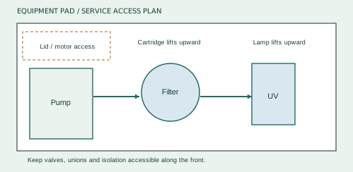
- Place the pump, filter and UV where each service part can be reached. Mark the actual equipment footprints on the pad before drilling or gluing.
- Keep the pump motor ventilated and the equipment area drained. Avoid roof runoff, persistent flooding and enclosed chemical storage.
- Keep isolation valves and unions on accessible faces. Leave room to lift lids and remove components.
- Plan cables and electrical isolation with the electrician. Equipment must not create a climbable route past the pool barrier.
The equipment-pad size follows the actual service envelopes. A generic rectangle is not sufficient if a lid or lamp cannot be removed.
02Mount and prime the pump
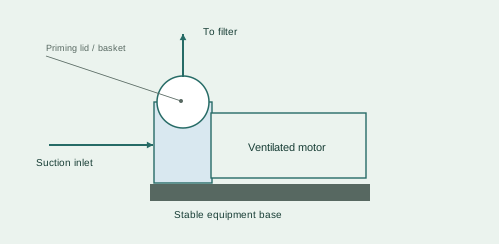
- Inspect the supplied pump, basket, lid seal and unions. Place it securely on the level pad without pipe strain.
- Connect suction to the inlet and discharge to the filter. Align the pipework; do not force the pump unions into position.
- Before first operation, fill the priming chamber as directed in the pump manual, fit the lid seal correctly and open the circulation path.
- Have the electrical supply and required bonding completed by the licensed electrician. Start only when primed; stop if it fails to establish circulation.
- Pump model / serial
- Priming completed
- Supply certificate reference
The prototype pump was a Davey Whisper W500. Match the installed pump model to its supplied operating instructions.
03Give the cartridge room to come out
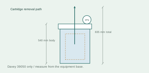
- For Davey CrystalClear 39050, reserve 835 mm total height from the base for cartridge removal. The body height is 540 mm. Leave useful access around the lid and gauge.
- Orient the chosen INLET toward pump discharge and connect OUTLET to the filtered return circuit. Close the unused inlet with the supplied cap.
- Use the supplied O-ring unions, clean seals and hand tightening. Support both pipe runs independently.
- Bleed trapped air during startup according to the filter manual and record the clean-filter pressure.
- Filter model / serial
- Clean-filter pressure (kPa)
- Cartridge-removal space checked
Dimensions shown are for 39050 only. A replacement model can have a different service envelope.
04Install the vertical UV chamber
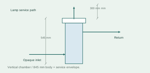
- Put Insnrg Ui in the filtered return line before any other sanitising device. Keep the chamber vertical and the inlet pipe opaque.
- Leave at least 300 mm clear above its top. A 545 mm chamber plus that clearance occupies 845 mm before mounting offsets or pipework.
- Mount the ballast under shelter; keep connections accessible. Arrange protected power and coordinated pump/UV operation with the electrician.
- Complete the wet leak check before enabling UV. Keep the housing assembled and never look at an exposed operating UV lamp.
- UV model / serial
- Overhead clearance measured
- Pump / UV timer coordination
Mount the ballast securely under shelter and beyond splash exposure, with its leads and isolation accessible.
05Reserve airflow for the Hi35
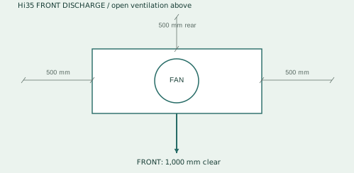
- For the front-discharge Hi35 manual 250926, keep at least 1,000 mm clear in front and 500 mm at each side and behind, with open ventilation above.
- Orient discharge away from nearby obstructions and avoid cold-air recirculation. Keep routine service access as well as airflow space.
- Set the unit level and provide condensate drainage. Do not carry or lift it by its water unions.
- Arrange licensed electrical connection. Refrigerant work belongs to qualified refrigeration personnel.
- Heat pump model / discharge type
- Front / side / rear clearances
- Condensate route
These clearances apply to the referenced front-discharge range, not a top-discharge model.
06Commission the heating option
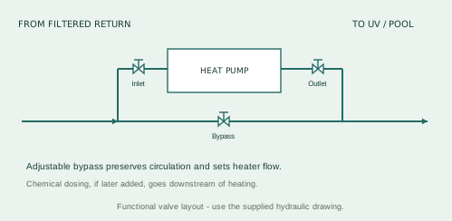
- Start circulation and check water flow before enabling the heater. Inspect its unions and bypass for leaks.
- Set the supplied bypass so the heater receives its model-required flow. Record inlet and outlet readings once operation is stable.
- Check that loss of circulation stops heating, following the manufacturer commissioning procedure. Restore the normal operating settings.
- Record model, serial, setpoint and bypass position. Keep controls accessible and show the owner how to isolate the heater safely.
- Inlet / outlet water temperatures
- Bypass setting / setpoint
- Flow-stop check
- Commissioning date / installer
Use the heat-pump manual for its operating range and flow adjustment; pool diameter alone does not determine the bypass setting.
Manufacturer instructions & references
Keep the instructions for your exact supplied model with this guide.
Davey CrystalClear manual ↗Insnrg equipment manuals ↗Completion checklist
- Outdoor airflow clearances met
- Drainage and service access ready
- Correct flow and bypass arrangement
- Qualified installation and electrical work complete
- Controls demonstrated
Help when you need it.
Installing the kit yourself or coordinating trades? Send your order number, photographs and the step you need help with.
contact@trublupools.com.au ↗